This manual is accurate and of high quality. It is only volume 2 of the service manual. This is schematic, parts lists, and exploded mechanical drawings. The theory of operation and the diss-assembly instructions are in volume 1. The unit can be tricky to dis-assemble portions of so the volume 1 manual can be important. The product description of the manual is accurate but it does not say anything about volume 1 and the image of the front page does clearly say Volume 2.
It has all the information you will need to fix it. The main circuit diagram is only A4 but being a PDF, you can print it to any size - I did it on two sheets of A3 and it didnt lose any detail - just made it readable when pinned up above the bench. I've found the fault, just need to buy some obscure bits to get it going again!
I cant fault the process, I paid for the manual in the morning and it was ready to download by lunch time.
Another excellent buy! File too clear and explanatory.
Text excerpt from page 76 (click to view)
2-9. Using the Extension Board
2-9. Using the Extension Board
The extension board is provided with the FVS-P1000 for checking and adjusting the processor board. . Extension board (EX-632): . Extension board (EX-670): A-8320-763-A A-8320-764-A For extending the board in front of the processor For extending the board at the rear of the processor
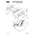
Extending the Front Side Board 1. 2. 3. 4. Open the door at the bottom of the unit. Loosen the four screws, and remove the front cover. (Refer to Section 2-8-1.) Open the eject levers at both ends of the board removed in the arrow direction. Holding the eject levers, pull out the board.
Eject lever
Eject lever
Board
5. Set the dip switches of the extension board according to the board extended. 6. Push in the extension board (EX-632) according to the guide rail. 7. Insert the board removed into the extension board.