|
|
|
Who's Online
There currently are 6041 guests online. |
|
Categories
|
|
Information
|
|
Featured Product
|
|
|
 |
|
|
There are currently no product reviews.
 ;
Irrespectively of this manual exist only germany language, it's useful - although i need some additional task to translate: My english is bad, but usable - but i really dont speak germany. :)
 ;
Excellent service from this company (including a total refund on an earlier purchase when through no fault of the company the manual was incomplete). I have purchased several manuals which I have been very satisfied with, as I am with this one. Highly recommended.
;
It was easy to order and received exactly what I needed. Only complaint would be the 24 hours you have to wait.
;
Manual was delivered in a timely manner and was all in English as advertised. The manuals I received when we moved into our flat were in German, Italian, and French. Having never used a steamer before, and not speaking/reading German very well, I needed an English Manual. this was a huge help.
;
Great Manual. This manual is available no where else. It was exactly what I was looking for. Only in German.
SECTION 3 MECHANICAL ADJUSTMENTS
Replacing the Thermal Head
1) Before replacing the head, print the stair-step pattern with the old head (faulty head).
Note 1: Only when the head is not entirely damaged with black or white lines. Note 2: To reproduce the stair-step pattern, refer to �Adjusting Method 1� in �4. Electrical Adjustments�.
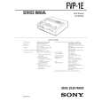
6) Remove the two screws 8 (PSW2.6 � 8) and remove the thermal head 9 from the heat sink 0. (Refer to Fig. 2)
Note: Do not remove the screw !� fixing the heat sink 0 and head arm !¡.
7) Replace the thermal head 9.
Note: Make sure that the silicon grease (white) does not stick onto the printing screen of the thermal head. If it does, remove with alcohol.
2) Remove the upper cabinet. (Refer to �2. Disassembly�.) 3) Remove the flat cables 1 (POHE13) and 2 (ADHE13) from the thermal head. (Refer to Fig. 1) 4) Remove the two screws 3 (BVTT2.6 � 6) and remove the harnesses 4 and fan holder 5. (Refer to Fig. 1) 5) Remove screw 6, (PS2.6 � 4) and remove the ribbon guide 7. (Refer to Fig. 2)
8) Assemble in the reverse order of steps 2) to 6). 9) Perform �Head Voltage Adjustment� of �4. Electrical Adjustments� (Page 4-3).
5 fan holder
3 two screws
(BVTT2.6 � 6)
7 ribbon guide 6 screw (PS2.6 � 4)
4 harness
!� two screws Note: Do not remove the screw. 8 two screws (PSW2.6 � 8)
0 heat sink
1 flat cable (POHE13)
2 flat cable (ADHE13)
9 thermal head
!¡ head arm
Fig. 2
Fig. 1
3-1 E
 $4.99 FVP1E SONY
Service Manual Complete service manual in digital format (PDF File). Service manuals usually contains circuit diagr…
|
|
|
> |
|