|
|
|
Who's Online
There currently are 5975 guests online. |
|
Categories
|
|
Information
|
|
Featured Product
|
|
|
 |
|
|
There are currently no product reviews.
 ;
I expect a wonderful result as alaways!!!!!!
Usually is much faster....
;
Wow very wonderful and clear!!!! I will always trust them
;
Providing the manual works fine, quickly and without any problems for an acceptable price. After printing the service manual it took me only a short time to repair my carradio from Clarion. Thank You! Greetings from Heiko
;
I was searching a way to modify the original phono-in entry (for connection of vynil disc player, with RIAA equalization) to a line-in entry (for connection of modern analog entries, eg. ipod, mp3player).
This service manual gave me the correct hints.
It contains very useful infos for repairing and modifing the hi-fi, such as disassembling instructions, block diagrams, schematic diagrams, PCB prints, replacement parts list.
Very good!
;
Great Job!!! clear and efficient as always!!
it is really nice to have peple that are doing such a good work!!!!!
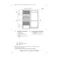
FDL-252T SECTION 3 CIRCUIT ADJUSTMENTS
[SETUP](A BOARD )
1. Apply a DC voltage of 4.5V±0.1V to the J601 terminal (DC input jack) on the A board. 2. With S601 on the A board at UHF position, set the User Control RV550(VOL) and RV901(BRT) on the H board to their mechanical centers.
< A BOARD ALIGNMENT > 3-1.VIF.AFT ROUGH ALIGNMENT (T201, T202)
[SETUP] 1. Set S601 on the A board to VHF position. 2. Apply no signal to JL119 (RF). 3. Connect a 1 k� resistor between JL09 (+5.0V) and JL13 (RF AGC). 4. Apply a sweep signal across JL12 (IF) and JL14(IF GND). (Fig. 3-1) Note : Set the sweep signal for JL12 to -30±5dBm. Keep the distance to the ATT output JL12 as short as possible.
[+5.0V ALIGNMENT (RV600)](A BOARD )
Using a digital voltmeter measuring the voltage between JL09 (+5.0V) and JL87 (A.GND). Adjust RV600 to obtain the value shown below. Standard Value = 4.55V± 0.02VDC S601 position = UHF position
[+30.0V CHECK](A BOARD )
Check the voltage across JL07 (+30.0V) and JL87 (A.GND) . Standard Value = 32.5V±2.5VDC
fo=45.75MHz±5kHz 75� 6dB SWEEP MARKER GENERATOR
0.01µF
ATT
JL12
[+7.5V CHECK](A BOARD )
Check the voltage across JL08 (+7.5V) and JL87 (A.GND) . Standard Value = 7.0V± 0.3VDC
Fig. 3-1
[-10.0V CHECK](A BOARD )
Check the voltage across JL10 (-10.0V) and JL87 (A.GND) . Standard Value = -9.8V± 0.6VDC
1. Connect an oscilloscope between JL86 (VIDEO) and JL87 (A.GND) and apply an external voltage (MGC) to JL26 to obtain a waveform as shown in Fig. 3-2 (make sure not to clip the extremely short portion).Adjust T202 so that the position at 45.75 MHz is the lowest point. Note : Align JL26 (MGC) external voltage for approximately a 1.0 Vp-p. Make sure that the JL26 (MGC) external voltage does not exceed 4.3VDC. 2. Remove the external voltage (MGC) from JL26. 3. Connect an oscilloscope between JL02 (AFT) and JL01 (D.GND) and make a rough adjustment of T201 so that waveform is close to zero at the 45.75 MHz position. 4. Remove the 1 kilohm resistor connected between JL09 (+5.0V) and JL13 (RF AGC).
- A board - (Component side)
J601 EXT ANT RV002 RV004
RV600
RV001 RV201
RV003
T201 T202
J601 DC IN JACK
1Vp-p
45.75MHz
0
Fig. 3-2
�6�
|
|
|
> |
|