|
|
|
Who's Online
There currently are 5985 guests and
3 members online. |
|
Categories
|
|
Information
|
|
Featured Product
|
|
|
 |
|
|
There are currently no product reviews.
 ;
buen manual con sus formas de onda y esquemas , completo y de buena calidad de imagen, es correcto.
;
This is exactly what I needed This was a hard one to find and I had already downloaded several for other Panasonic radios but none matched my radio.
Although my radio is the LBE model the LBS is the same.
A very good quality manual with every thing you should get in it
;
el manual es correcto , completo y de buena calidad aunque algun esquema esta excesivamente diseccionado.
;
muy buen manual con multiples graficos y formas de onda ademas de muy completo y bien presentado.
 ;
As Always these people were very rapid and efficient. A great job helping hobbiest and workers!!! Thank you a lot!
2-4-2. Switch, Indicators, Audio and Communication Circuit Check by an Oscilloscope
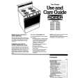
1. Connect the pin 7 of CN1 on the AU-254 board to the + terminal of the power supply, and the pins 1 and 2 of CN1 to GND of the power supply. Use the modified RK-8XXX cable to facilitate the check required. (Refer to step1 in 2-4-1. Switch, Indicators and Audio Circuit Check.) 2. Connect the pin 4 of CN1 on the AU-254 board to GND of the power supply. 3. Set a DC out voltage to +15 V, and turn on the power switch. 4. Two seconds later, all response indicators (D1 through D6 on the SW-952 board) flash. 5. Disconnect the pin 4 of CN1 on the AU-254 board from GND of the power supply. 6. With transmitting �55H� code from the pin 3 of IC1 (TxD terminal) on the SW-952 board, all response indicators light. With all response indicators flashing, that is, without lighting, it is abnormal. Check the signals between the pin 1 of IC1, the pin 3 of IC1 and the pin 4 of CN1 on the AU-254 board. 7. (a) Switches and indicators check Perform the same step as step 7(a) in 2-4-1. Switch, Indicators and Audio Circuit Check. (b) Audio circuit check Perform the same step as step 7(b) in 2-4-1. Switch, Indicators and Audio Circuit Check. (c) Communication circuit check Using an oscilloscope, confirm that �55H� code is transmitted to the pin 4 of CN1. With transmitting �55H� code to the pin 4 of CN1, it shows the following waveform on the oscilloscope.
Start bit
2-4-3. Indicators, Audio and Communication Circuits Check by EA-80 connected to LLC-8000
1. Press the POWER switch on the LLC-8000 to turn the total LLC-8000 system on. (Do not press the ATTEND button on the LLC-8000. Not pressing the ATTEND button does not light the indicator located at the left-above the monitor button on the LLC-8000.) 2. Check switches, indicators and audio circuit by the same steps as steps 3 through 7 in 2-4-1. Switch, Indicators and Audio Circuit Check. 3. Communication circuit check. When the communication is established, the indicator that shows the student unit, EA-80, being checked and located at the left-above the monitor button on the LLC-8000, lights. 4. Press the POWER switch on the LLC-8000 to turn the system off.
b6
b�
TXD TERMINAL "55 H"
5 0.42 msec
5
H
2-4
Stop bit
1
0
1
0
1
0
1
EA-80
|
|
|
> |
|