|
|
|
Who's Online
There currently are 5261 guests online. |
|
Categories
|
|
Information
|
|
Featured Product
|
|
|
 |
|
|
There are currently no product reviews.
 ;
just what i was seeking .had a password issue but the review allowed me to circumvent and download was great
;
Great manual, great price. Has a few of the basic operating instructions that most service manuals leave out. Complete instructions for disassembling board by board, safety precautions, schematics, complete parts list.
;
I am very pleased with the service manual for my RT-909. This was an easy purchase and great procuct, and much cheaper than other venues i had looked at. This web site is now listed in my favorites list. KEEP UP THE GOOD WORK. THANKS. J. BROWN
;
A very well written and easy to understand manual.
;
There was no problem at all.After paying i had to wait only a few hours,than i could
download the manual in best pdf-quality.
Thank You !
SECTION 3 TEST MODE
3-1. OUTLINE
This set has the test mode in which the pick-up can be operational checked and the video signal can be verified.
3-3. VIDEO SIGNAL VERIFICATION
3-3-1. Setting the test mode 1. Switch positions OPEN switch (S801) : OPEN HOLD switch (S804) : OFF AVLS switch (S893) : OFF 2. Short the TEST terminal TAP801(TEST) by soldering it. Remove the solder from the TAP901(V-TEST) and connect the terminal to the TP945 (VDD) with a 47 k� resistor. 3. Supply 4.5V DC from the DC jack (J401). 3-3-2. Releasing the test mode 1. Open the TEST terminal TAP801(TEST). Remove the resistor from the TAP901 (V-TEST) and short the terminal by soldering it. 2. Turn the power OFF. 3-3-3. Operational checks 1. Connect the TP931 to the TP945 (VDD) with a 47 k� resistor (NTSC mode). 2. Press the O RETURN key once. 3. Verify that a 100% white pattern is output from the VIDEO OUT (J901). 4. Press the O RETURN key once (output off). 5. Connect the TP931 to the TP919 (GND) (PAL mode). 6. Press O RETURN key once. 7. Verify that a 100% white pattern is output from the VIDEO OUT (J901). 8. Press the O RETURN key once (output off). 9. Open the TP931.
3-2. PICK-UP OPERATIONAL CHECKS
3-2-1. Setting the test mode 1. Switch positions OPEN switch (S801) : OPEN HOLD switch (S804) : OFF AVLS switch (S893) : OFF 2. Short the TEST terminal TAP801 (TEST) by soldering it. Remove the solder from the TAP901 (V-TEST) and open the terminal. 3. Supply 4.5 V DC from the DC jack (J401). 3-2-2. Releasing the test mode 1. Open the TEST terminal TAP801 (TEST) and short the TAP901 (V-TEST). 2. Turn the power OFF. 3-2-3.Operational checks 1. When a specific key is operated: Contents of the operation. KEY ((LCD DISPLAY)) u x CHG > NEXT Spindle on. Tracking servo off. ((UP 00 03)) All servo off. Mute on. ((10 different displays are repeatedly presented.)) Moves the pick-up to the outside (with the open switch open). Tracking servo off. Mute on. ((Among 10 different displays, the display when the key is pressed is held.)) Moves the pick-up to the inside (with the open . PREV switch open). Tracking servo off. Mute on. ((Among 10 different displays, the display when the key is pressed is held.)) 2. In play mode � Press the u key: KEY Contents of the operation. ((LCD DISPLAY)) Tracking servo on. Mute off. Each time this key is pressed, the display changes as follows: x1 speed t x2 speed t x3 speed t x4 speed t x1 speed (( 01 00 01)) t ((02 00 02)) t ((03 00 03)) t ((04 00 04)) SELECT REPEAT/ ENTER Each time this key is pressed, the display changes as follows: Tracking gain up. Emphasis on. LCD back light on h Tracking gain down. Emphasis off. LCD back light off
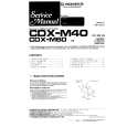
1.0 ± 0.2Vp-p H
Fig. 100% white pattern
Adjustment Location: See page 10.
PLAY MODE
�9�
|
|
|
> |
|