|
|
|
Who's Online
There currently are 6004 guests online. |
|
Categories
|
|
Information
|
|
Featured Product
|
|
|
 |
|
|
There are currently no product reviews.
 ;
Very helpful and complete manual. Maybe only one negative is schematics have sometimes unreadable name of the parts. But it's not a big problem.
 ;
Excellent high quality schematics brought my old Heidelberg back to life. Fast download at a reasonable price. Thanks.
;
This document is just what I was looking for, it´s very useful, it contains adjustment procedures for the final stage of the power amp and also
has a complete wiring diagram and description of the main semiconductors used in the design.
;
Dear Sirs,
Thank you for the fast support, the manual does provide all necessary information to repair the radio. All schematics are in a good quality for reading.
The manual fits 100% to my requirements as a technican.
Kind regards Thomas
;
the big video recorder format s-vhs many features delicate in loading system of the cassette. Such machines are no longer manufactured, it would be too expensive.
6-9.
IC PIN FUNCTION
Pin Name Vss X1 X2 RESET P33 NOTE P32 NOTE P31 NOTE P30 NOTE P81 P80 P23 P22 P21 P20 P03 P02 P01 P00 IC VDD P10 P11 P12 P13 P73 P72 P71 P70 P63 P62 P61 P60 P50 to P53 I/O � I I I I/O I/O I/O I/O I/O I/O I/O I/O I/O I/O I I/O I/O I � � I I I I I/O I/O I/O I/O I/O I/O I/O I/O I/O Programmable 4-bit input/output port (PORT6). Input/output can be specified in units of bit. Connection of the internal pull-up resistors can be specified by software in units of 4-bits. N-ch open drain 4-bit input/output port (PORT5). Pull-up resistor can be internally connected in units of bit (Mask option). 13 V withstand voltage in the open drain connection. 4-bit input/output port (PORT7). Connection of the internal pull-up resistors can be specified by software in units of 4-bits. Internally connected. Connect this pin to VDO directly. Positive power supply. 4-bit input port (PORT1). Connection of the internal pull-up resistors can be specified by software. P10/INT0 have the noise rejection function. 4-bit input port (PORT0). Connection of the internal pull-up resistors for P01 to P03 can be specified by software in units of 3-bits. 4-bit input/output port (PORT2). Connection of the internal pull-up resistors can be specified by software in units of 4-bits. Ground potential. External crystal/ceramic oscillator for system clock oscillation is connected to this pin. In the case of external clock, connect it to X1 and connected its inverted phase signal to X2. System reset input. (Low-level active). Programmable 4-bit input/output port (PORT3). Input/output can be specified in units of bit. Connection of the internal pull-up resistors can be specified by software in units of 4-bits. 2-bit input/output port (PORT8). Connection of the internal pull-up resistors can be specified by software in units of 2-bits. Function
� TUNER BOARD IC8 µPD754302GS
Pin No. 1 2 3 4 5 6 7 8 9 10 11 12 13 14 15 16 17 18 19 20 21 22 23 24 25 26 27 28 29 30 31 32 33 to 36
Note 1. The white round mark (O) indicated Schmidt trigger input. 2. LED can be directly driven. 3. When the internal pull-up resistor is not used by mask option (when it is used as N-ch open drain input port), the low level input leak current increases when input instruction and bit operation instruction are performed.
� 39 �
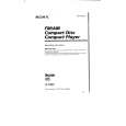 $4.99 D-T405 SONY
Owner's Manual Complete owner's manual in digital format. The manual will be available for download as PDF file aft…
|
|
|
> |
|