|
|
|
Who's Online
There currently are 5915 guests online. |
|
Categories
|
|
Information
|
|
Featured Product
|
|
|
 |
|
|
There are currently no product reviews.
 ;
A site where discontinualed schematic diagrams and back dated information can be found on discontinued radios tv's and any electronic equipment can be found. Newer manuals either Service and operating manuals. Radio amateurs should find this site a great source for ham radio equipment manuals. I will return to this site should I need information on any electrical equipment. priced easy to download in a PDF format and print pages need to undertake the repair.
;
Quality scan of the original. All the detail necessary to troubleshoot, repair and adjust the unit. I'm sure I will be downloading more manuals in the future as the need arises.
;
Exactly as described, a Service Manual complete with the schematics and PCB layout delivered in a timely manner. Many thanks for the great service.
 ;
some of the writing is a bit blur but the part in the schmatic was great and i have fixed the machine thanks
;
Well.. I'd searched for this manual and although I found many copies online I was pleased to find your website with a well balanced pricing system and easy to search and follow links. That together with the very quick response time was just what I was looking for.. being a very impatient tech.. ;-) I had the service manual in front of me within a short time.
Bookmarked.. and you can bet I will always come here first for my service & user manuals..
best regards
Ed(Tony) Foley
G7WHK
DSC-P51/P51M
1-1-4. Precautions 1. Setting the Switch Unless otherwise specified, set the switches as follows and perform adjustments. 1. Mode Dial .......................................... CAMERA 2. ZOOM switch (PK-062 board S252, S254) .............. WIDE end 3. EV (Menu display) ............................ 0EV 4. DSIPLAY/LCD ON/OFF button (PK-062 board S256) ......................... OSD OFF 5. WB (WHITE BALANCE) (Menu display) ................................... AUTO 6. P.EFFECT (Menu display) ................ OFF 7. VIDEO OUT (SET UP setting) ......... NTSC
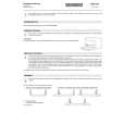
Yellow Cyan Green White Magenta
2. Order of Adjustments Basically carry out adjustments in the order given. Color bar chart (Color reproduction adjustment frame)
H C
Blue
Red
Electronic beam scanning frame
C=D
D
Magenta Red Blue Yellow Cyan
CRT picture frame
V AB A=B BA Enlargement
Fig. b (monitor TV picture)
Green
Difference in level
Adjust the camera zoom and direction to obtain the output waveform shown in Fig a and the monitor TV display shown in Fig. b.
B
A
Fig. 5-1-7
3. Subjects 1) Color bar chart (Standard picture frame). When performing adjustments using the color bar chart, adjust the picture frame as shown in Fig. 5-1-7. (Standard picture frame) 2) Clear chart (Standard picture frame) Remove the color bar chart from the pattern box and insert a clear chart in its place. (Do not perform zoom operations during this time) 3) Chart for flange back adjustment Join together a piece of white A0 size paper (1189mm � 841 mm) and a piece of black paper to make the chart shown in Fig. 5-1-8. Note: Use a non-reflecting and non-glazing vellum paper. The size must be A0 or larger and the joint between the white and black paper must not have any undulations.
White
White 841 mm Black
1189 mm
Fig. 5-1-8
5-6
 $4.99 DSCP51 SONY
Owner's Manual Complete owner's manual in digital format. The manual will be available for download as PDF file aft…
|
|
|
> |
|