|
There are currently no product reviews.
 ;
Print was clear and easy to read. Thank you Joe joeoldaudio
 ;
Very great deal. In a few minutes a have the manual, that I needed. Thanl you very much
 ;
Manual was complete. Received it quickly. No problems
 ;
Product was very good. Received quickly and complete
 ;
The Sony AV-3600 service manual was what I needed for the repair of this unit
Thanks for the good service
Dave
DSC-P10/P12
1-3. PRECAUTION ON REPLACING THE VIDEO LENS OR THE SY-83 BOARD
The DSC-P10/P12 uses the position sensor to detect the zoom position. Accordingly, the zoom position will vary if the position data changes due to the replacement of the video lens or the SY-83 board, thus causing the video lens to collide against the mechanism end when the power is turned off. Though the position data is calibrated at the �Flange Back Adjustment�, add the following work when making an adjustment at the replacement of video lens to prevent a collision of video lens. When Replacing the Video Lens 1) With current video lens assembled, turn the power on, and set the data of page: 6F, address: 3E to �FF�, then turn the power off. 2) Replace the video lens with a new one, turn the power on, and perform the �Flange Back Adjustment�. Thus, new position data will be written. When Replacing the SY-83 Board 1) Replace the SY-83 board with a new one, set the mode dial to �PLAY�, turn the power on, and set the data of page: 6F, address:3E to �FF�, then turn the power off. 2) Set the mode dial to �CAMERA�, turn the power on, and perform the �Flange Back Adjustment�. Thus, new position data will be written.
1-4. NOTE IN LENS FRAME INSTALLATION
When tightening a screw, have both sides of the lens block assembly so as not for the load to depend.
M1.7 � 4 Lens block assembly Lens frame
M1.7 � 4
1-2
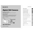
 $4.99 DSC-P12 SONY
Owner's Manual Complete owner's manual in digital format. The manual will be available for download as PDF file aft…
|
