|
|
|
Who's Online
There currently are 6043 guests online. |
|
Categories
|
|
Information
|
|
Featured Product
|
|
|
 |
|
|
There are currently no product reviews.
 ;
The manual was of good quality with high resolution schematic diagrams.
;
The manual was very clear and contained all the information I was looking for. My dishwasher is working again because of this servicemanual!
;
Quality scan, great manual. I solved my problem with this manual.
 ;
The AKAI 1720 model reel to reel tape recorder described in this Manual is quite an old unit - circa late 1960's. As a consequence, the description of the mechanical details - and adjustments thereof - is quite critical. The manual does this quite well. The schematics are also well presented and have detailed PCB overlays. Probably the only negative is that some half-tone detail has been lost from the original manual as it has been scanned in simple B&W.
;
Perfect source for service manuals: fast and professional transaction; high quality, perfect readable and largely scaleable PDF; complete schemes, diagrams and spare part list. Tnx a lot, cu again!!!!
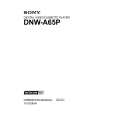
4-1-3. Video Tracking Check and Adjustment
(4) Turn the height adjustment nut of TG-3 counterclockwise by one to two turns so that the tape does not in contact with the upper flange of TG-3. (5) Turn the height adjustment nut of TG-4 clockwise so that the tape does not in contact with the lower flange of TG-4. (6) Turn the zenith adjustment screw of the AT head so that the right portion of the RF envelope waveform makes 50% to 100% of the maximum output level. (Fig. 1) At this time, check that the tape does not in contact with both upper flange of TG-3 and lower flange of TG-4. If the tape contacts either flange, repeat step (4) or (5). If the tape moves upward or downward following the guide flange movement, perform the following adjustment. This trouble cause is uneven tape tension at upside or downside of the tape caused by AT head zenith. . If the tape moves upward at TG-3: Turn the zenith adjustment screw counterclockwise. . If the tape moves downward at TG-4: Turn the zenith adjustment screw clockwise. (7) Turn the height adjustment nut of TG-3 so that the tape is in contacts with the upper flange and the RF envelope waveform becomes flat. (Fig. 2) At this time, the tape does not in contact with the lower flange of TG-4. If the waveform does not become flat, perform the check and adjustment below. 1 Clean the drum lead with a bamboo stick. (Refer to Section 5-2-4 of the maintenance manual part 1.) 2 Press down the tape by bamboo stick very lightly and check that the tape is running without aparting from the drum lead. 3 If the waveform does not become flat even though steps 1 and 2 mentioned above are performed, adjust the height of TG-3 so that the RF envelope waveform is nearly flat within the range of the specification 12 shown in the Fig.3. At this time, do not overpress the tape at TG-3. � Continued on the next page. �
Marker
TG-4
AT head
TG-3
. Alignment tape : SR2-1/SR2-1P (00:00 to 15:00)
AT head
Zenith adjustment screw
. Alignment tape : SR2-1/SR2-1P (00:00 to 15:00) (Tracking VR : Effective) : D112/SS-83 board lights up <Fig. 1> RF max
80%
50% ~100% Marker
<Fig. 2> Be flat If the pressure against the tape at TG-3 is too much, the waveform becomes as shown in the right figure. (NG)
4-24
DNW-A65/A65P
|
|
|
> |
|