This scanned manual is well done in that most all the pages except for one is straight and clear- the way I would do them. One page was upside down but that happens. For the money that is charged on this site you get a pretty good deal. Now with complex repairs, I still prefer to us paper manuals which I have to buy at stereomanuals but the one I got here was much less than the $45 he was charging but this is a larger than normal manual for three different units. I am a picky manual user because I have used original manuals from Sony and Teac.
Content A4 and A3 format pages. Exactly what I needed to restore my old receiver.
Text excerpt from page 13 (click to view)
5-2.
Installation to the Projector
5-2-1. Installing to CENTURY JJ (Strong International)
Required Parts
Notes on Installation . Place the DFP-R3000 in the upright position (not sideways nor tilted) and position the reader (part of the drum where the LEDs are located) of the DFP-R3000 more than 24 frames but within 119 frames from the picture gate of the projector. However the film speed must be stable (within ± 5 %) when the first image frame passes by the reader of the DFP-R3000. . The tension of the film that is supplied to the DFPR3000 during film running is set to 0.5 to 59 N (50 to 600 fg). Adjust so that the tension is within the above range between the beginning and end of the supplied film. Required Tools Path adjustment tool (Sony part No. J-6510-220-A) 35 mm Film Phillips screwdriver Nut driver (d = 5 mm) Hexagon screwdriver (across ; 3 mm)
Adapter (A) ; 1 (Supplied with DFP-R3000) Hexagon cap screw (3/8-16) ; 2 (Supplied with DFP-R3000) Wave washer ; 2 (Supplied with DFP-R3000) Screw (PSW4 x 12) ; 4 (Supplied with DFP-R3000) Procedure
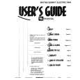
Step 1. Installing the Adapter (A) to the Projector
1. Remove REEL ARM or platter guide roller of supply reel side of the projector. 2. Attach the adapter (A) tentatively to the projector using the two hexagon cap screws (3/8-16) 1 and wave washers. n Fixing hole of adapter (A) varies depending on the projector to be used. (See the figure below.) 3. Attach the path adjustment tool tentatively to the adapter (A) with the screws (PSW4 x 12) 2 as shown in the figure.
Path adjustment tool