|
|
|
Who's Online
There currently are 5719 guests online. |
|
Categories
|
|
Information
|
|
Featured Product
|
|
|
 |
|
|
There are currently no product reviews.
 ;
I really like this manual and it's reliable.I found and bought easly.thank you.
;
Thank you very much. the Instruction corresponds to my expectations. Sent it in time. I don't regret that paid money.
;
Good quality. Quick service. I recommend to everyone.
;
Very good quality scan of the document. I am very pleased with what I got.
;
PDF Contains
Technical Data, Mechanical data, Detailed Circuit diagram with components value, PCB layout. Actual PCBs Print. Component List, Spare parts code list and Input output detail. It cover LBB1211, LBB1212, LBB1213, LBB1216, LBB1217.
It is the actual Service Manual for SQ10
SECTION 5 ELECTRICAL ADJUSTMENTS
Precautions for Adjustment 1. Before beginning tracking balance adjustment, set the equipment to service mode. After the completion of adjustment, be sure to reset the service mode. For more information, see �Service Mode (service program)� on page 9. 2. Perform adjustments in the order given. 3. Use YEDS-18 disc (Part No.: 3-702-101-01) unless otherwise indi- cated. 4. Power supply voltage requirement.: DC 4.5 V HOLD switch : OFF VOLUME switch : Minimum RESUME switch : OFF ESP switch : OFF AVLS switch : OFF 5. For adjustment, the remote comcommander is required. Before Beginning Adjustment Set the equipment to service mode (See page 9) and check the following. If there is an error, repair the equipment. � Checking of the sled motor 1. Open the upper panel. 2. When continuously pressing ( (+) or = key on the remote commander, and check that the optical pick-up can move smoothly without sluggishness or abnormal noise in innermost periphery � outermost periphery � innermost periphery. (At this time, the PLAY status is active.) ( (+) key on the remote commander:The optical pick-up moves outwardly. = key on the remote commander: The optical pick-up moves in- wardly. � Checking of focus searching 1. Open the upper panel. 2. Press the ( (+) key on the remote commander. (Focus searching operation is activated continuously.) 3. Check the object lens of the optical pick-up for smooth up/ down motion without sluggishness or abnormal noise. 4. Press the p key. Check that focus searching operation is deactivated. If not, again press the p key slightly longer. Focus bias Check Condition: � Hold the set in horizontal state. Check Procedure:
oscilloscope (AC range) MAIN board TP536 (RFO) TP537 (VC) (See page 12) 2k�
+ �
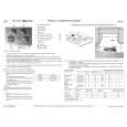
1. Set the equipment to service mode stop state. (See page 9.) 2. Connect the oscilloscope to the test point TP536 (RFO) of the MAIN board. 3. Move the optical pick-up to the center by pressing the ( (+) and = keys. 4. Put the disc (YEDS-18). 5. Press the ^ key. From focus searching, focus is turned ON while entering CLV drawing-in mode. Tracking and sled are turned OFF. 6. Press the PLAY MODE key. (Both tracking and sled are turned ON.) 7. Check the oscilloscope waveform is as shown below. A good eye pattern means that the diamond shape (�) in the center of the waveform can be clearly distinguished. RF SIGNAL REFERENCE WAVEFORM (EYE PATTERN)
VOLT/DIV : 200 mV (With the 10:1 probe in use) TIME/DIV : 500 ns
RF level 1.0 ± 0.2 V
To watch the eye pattern, set the oscilloscope to AC range and increase the vertical sensitivity of the oscilloscope for easy watching.
VCC Adjustment Adjustment Procedure:
digital voltmeter (DC range) MAIN board L401 (RV301 side) (See page 12) + �
8. Stop revolving of the disc motor by pressing the p key. 9. After the completion of adjustment, reset service mode. (See page 9.) Check Location: MAIN Board (See page 12.)
1. Set the equipment to service mode stop state. (See page 9.) 2. Connect the digital voltmeter to L401 (RV301 side) of the MAIN board. 3. Adjust RV401 on the MAIN board so that the reading on digital voltmeter goes 2.7 to 2.8 V. 4. After the completion of adjustment, reset service mode. (See page 9.) Adjustment Location: MAIN board (See page 12)
� 10 �
 $4.99 D-E900 SONY
Owner's Manual Complete owner's manual in digital format. The manual will be available for download as PDF file aft…
|
|
|
> |
|