|
|
|
Who's Online
There currently are 5657 guests and
1 member online. |
|
Categories
|
|
Information
|
|
Featured Product
|
|
|
 |
|
- GENERAL
- SERVICE NOTE
- DISASSEMBLY
- SERVICE MODE
- ELECTRICAL ADJUSTMENTS
- DIAGRAMS
- Block Diagram
- Printed Wiring Boards
- Schematic Diagram
- IC Pin Function Description
- EXPLODED VIEWS
- ELECTRICAL PARTS LIST
There are currently no product reviews.
 ;
I am very happy regarding the online purchase of this manual from Owner-Manuals.com as with this I could set right my Denon CD player and Amplifier.
I once again sincerely thank them for the prompt service which was rendered to me.
N. Shanker
;
More than pleased with my prurchase, very good product for the price.
;
Manual-link came 30 minutes after having paid for an extremely rare (40 years old) item (sony icr-120) and helped me to get the radio rework again. So really good help for me, fast and reliable delivery and -taken that into consideration- a very reasonable price for that service. So thanks again! Mike, Germany
 ;
Some of the pictures in this manual are a bit irritating. I had to dissassemble the unit and some of the screws have different threads, which is not mentioned in this manual. Also some of the drawings of the boards look different than the actual boards.
After all, the manual was very useful. I was able to recalibrate the capstan drive and it is working fine again.
;
This manual is very good. 303 pages scanned in a very high resolution. My camera has bad, leaking capacitors which all of the V5000 models are suffering from these days.
There is a huge part list with all capacitors, transistors etc. in this manual which helped me a lot. Otherwise I would not have been able to buy replacement parts.
The dissassembly guide is very enormous and detailed. Unlike on the Panasonic MS1 manual I downloaded here it actually looks like the real parts look. And the screws are labeled correctly, so you shouldn't have any left after the repair. ;)
SECTION 5 ELECTRICAL ADJUSTMENTS
Precautions for Adjustment 1. Before beginning adjustment, set the equipment to service mode. After the completion of adjustment, be sure to reset the service mode. For more information, see �Service Mode (service program) � on page 8. 2. Perform adjustments in the order given. 3. Use YEDS-18 disc (Part No.: 3-702-101-01) unless otherwise indicated. 4. Power supply voltage requirement: DC2.5 V in battery terminal VOLUME knob : Minimum RESUME switch : OFF ESP switch : OFF AVLS switch : NORMAL HOLD switch : OFF Before Beginning Adjustment Set the equipment to service mode (See page 8) and check the following. If there is an error, repair the equipment. � Checking of the sled motor 1. Open the upper panel. 2. Press the + and = keys and check that the optical pickup can move smoothly without sluggishness or abnormal noise in innermost periphery n outermost periphery n innermost periphery + :The optical pick-up moves outwardly. = :The optical pick-up moves inwardly. � Checking of focus searching 1. Open the upper panel. 2. Press the ^ key. (Focus searching operation is activated continuously.) 3. Check the object lens of the optical pick-up for smooth up/ down motion without sluggishness or abnormal noise. 4. Press the p key. Check that focus searching operation is deactivated. If not, again press the p key slightly longer. VCC Adjustment Adjustment Procedure:
digital voltmeter (DC range) MAIN board TP401 (VCC) (See page 11) + �
Focus bias Check Condition: � Hold the set in horizontal state. Check Procedure:
oscilloscope (AC range) MAIN board TP522 (RFO) TP520 (VC) (See page 11) 2k�
+ �
1. Set the equipment to service mode stop state. (See page 8.) 2. Connect the oscilloscope to the test point TP522 (RFO) of the MAIN board. 3. Move the optical pick-up to the center by pressing the + and = keys. 4. Put the disc (YEDS-18). 5. Press the ^ key. From focus searching, focus is turned ON while entering CLV drawing-in mode. Tracking and sled are turned OFF. 6. Press the PLAY MODE key. (Both tracking and sled are turned ON.) 7. Check the oscilloscope waveform is as shown below. A good eye pattern means that the diamond shape (�) in the center of the waveform can be clearly distinguished. RF SIGNAL REFERENCE WAVEFORM (EYE PATTERN)
VOLT/DIV : 200 mV (With the 10:1 probe in use) TIME/DIV : 500 ns
RF level 1.0 ± 0.2V
To watch the eye pattern, set the oscilloscope to AC range and increase the vertical sensitivity of the oscilloscope for easy watching.
8. Stop revolving of the disc motor by pressing the p key. 9. After the completion of adjustment, reset service mode. (See page 8.) Check Location: MAIN Board (See page 11.)
1. Set the equipment to service mode stop state. (See page 8.) 2. Connect the digital voltmeter to TP401 (VCC) of the MAIN board. 3. Adjust RV401 on the MAIN board so that the reading on digital voltmeter goes 2.75± 0.05 V. 4. After the completion of adjustment, reset service mode. (See page 8.) Adjustment Location: MAIN board (See page 11)
�9�
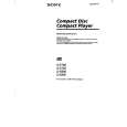 $4.99 D-E700 SONY
Owner's Manual Complete owner's manual in digital format. The manual will be available for download as PDF file aft…
|
|
|
> |
|