|
|
|
Who's Online
There currently are 5974 guests online. |
|
Categories
|
|
Information
|
|
Featured Product
|
|
|
 |
|
|
There are currently no product reviews.
 ;
This is the correct service manual of SHARP RX-100H(BK) DAT.
;
The ervice manual for my 1982 Kenwood KR-1000 receiver is great! Full detail on all circuits with part number detail. I will definately be ordering more manuals for my other vintage equipment! Order was fulfilled quickly! Very efficient ordering process! Thnaks for your help! Great site!
 ;
Everything in the manual was excellent except for a couple of pictures of specific areas in the unit that were a little dark. Owners Manuals re-sent the pdf file & the problem was corrected. Excellent product! George
;
Thanks for offering this item at such a good price. Proved handy in identifying the part I was looking for my set.
Thanks again.
;
This is the original manufacturers service manual, with detailed info on the circit boards, explosion drawings of all parts in assembly order, and tuning instructions. The only thing missing is the information on the dimensions of the various drive belts. mail me if you need them. gcrossman_at_aol.com
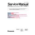
4-3. Drum Base Assembly, Drum Earth
1. Removal procedure
1) Remove the capstan flexible board and flexible wiring board (FP-300) from the holders X, Y and Z in the direction of the arrow. Remove the drum assembly. (Refer to section 4-1.) Remove the screw (M1.4 � 2.5) 2. Remove the claw D of the guide rail T2 3 from the hole E of the drum base assembly in the direction of the arrow F. Remove the three screws (M1.4 � 2.5) 4. Remove the drum base assembly 5 in the direction of the arrow. Remove the screw (screw assy PW M1.7 � 2.6) 6. Remove the drum earth 7 and earth spacer 8.
2. Attachment procedure
1) Attach the ground spacer 8 and drum ground 7 with the screw (screw assy PW M1.7 � 2.6) 6. Tightening torque: 0.078 ± 0.01 N�m (0.8 ± 0.1 kgf�cm) Align the drum base assembly 5 with the reference pin and tighten the three screws (M1.4 � 2.5) 4 in the order of G, H and I. Insert the claw D of the guide rail T23 into the hole E of the drum base assembly 5 and tighten the screw (M1.4 � 2.5) 2. Tightening torque: 0.078 ± 0.01 N�m (0.8 kgf�cm) Remove the drum assembly. (Refer to 4-1.) Attach the flexible wiring board (FP-300) 1 and capstan flexible board to the drum base assembly. Clean the tape running path. (Refer to 2-2.)
2) 3) 4) 5) 6) 7) 8)
2)
3)
4) 5) 6)
G F
hole E
H I 4 Three screws (M1.4 � 2.5) 5 Drum base assembly
2 Screw (M1.4 � 2.5)
Guide rail (T2) Remove the guide rail (T2) in the direction of the arrow F.
Claw D
Drum base assembly
3 Guide rail (T2)
Remove the flexible board in the direction of the arrow A B C. FP-300 flexible board
C B 6 Screw (screw assy PW M1.7 � 2.6) 7 Drum ground Z Y X A 8 Ground spacer
Two dowels
Claw D
Capstan flexible board
1 FP-300 flexible board, Capstan flexible board
Fig. 4-3.
� 16 �
|
|
|
> |
|