|
|
|
Who's Online
There currently are 6043 guests online. |
|
Categories
|
|
Information
|
|
Featured Product
|
|
|
 |
|
|
There are currently no product reviews.
 ;
The Service Manual for the Kenwood KR-V55R provided by owner-manuals.com was as described/advertised. The contents provided the necessary information to effect a diagnosis of the unit. The schematics above all else was instrumental in tracing the the signal flow from component to component.
 ;
This manual was the factory original. Excellent value and contained all the details I needed. Easy dowwnload provided the information when I needed it.
;
Impeccable, document très complet. Perfect, i get all i need. All schematic are correct. Thanks
;
The manual is of better quality compared to other. I found it less expensive and therefore it it is the best buy cost vs quality.
;
I bought the service-manual of the sony ICB-1020(an old transmitter-receiver) at "www.Owners-Manual.com", I found the service-manual for a fairly cheap price(in comparison with other sellers). I filled in some questions, payed the order with Ideal, and within 24 hours I had my service manual. I was very happy:In no time I had my service-manual and everything, but literally everything was noted down in the manual; the electronic scheme, the parts list, etcetera.
A very practical, reference-document.
SERVICE NOTE
1. POWER SUPPLY DURING REPAIRS
Battery switch
In this unit, about 10 seconds after power is supplied (8.4V) to the battery terminal using the service power cord (J-6082-223-A), the power is shut off so that the unit cannot operate. This following two methods are available to prevent this. Take note of which to use during repairs.
Method 1.
Connect the servicing remote commander RM-95 (J-6082-053-B) to the LANC jack, and set the remote commander switch to the �ADJ� side.
Method 2.
Press the battery switch of the battery terminal using adhesive tape, etc.
Method 3.
Use the DC IN terminal. (Use the AC power adaptor.)
Battery terminal � DC IN terminal Battery terminal �
Battery SIG terminal
2.
1 2 3 4 5 6
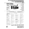
TO TAKE OUT A CASSETTE WHEN NOT EJECT (FORCE EJECT)
Refer to 2-1. to remove the front panel assembly. Refer to 2-1. to remove the cabinet (R) assembly. Refer to 2-1. to remove the battery panel assembly. Refer to 2-1. to remove the cabinet (L) assembly. Disconnect CN901 of VC-213 board. Add +5V from the DC POWER SUPPLY and unload with a pressing the cassette lid.
6 Pull the timing belt in the direction of arrow A with a pincette while pressing the cassette lid (take care not to damage) to adjust the bending of a tape.
Press the cassette lid to rise the cassette compartment
Pincette Timing belt [DC power supply] (+5V)
7 Let go your hold the cassette lid and rise the cassette compartment to take out a cassette.
Loading motor
Disconnect CN901 of VC-213 board. Timing belt Adjust the bending of a tape
�8�
|
|
|
> |
|