Up to now you are the BEST! Prompt-efficient and so reasonable ! I have been after SONY service manual for quite some time !Thank you very much ! I can recomend your service to
all my collegagues ! V.Bergfield .
This is a very good quality print (scan) of the original SONY service manual. The original from Sony is on very thin paper. Nevertheless it is very clear and sharp and excellent readable. I'm very satisfied to have now this rare document. I've looking for it many years (infrequent). It contains very detailed circuit diagrams, exploded views, part lists, PCB view with good readable connection lines. Very recommended.
Excellent product, very clear print. Detailed circuit and assembly diagrams - this enabled me to repair my CD player with confidence. I highly recommend this site.
Text excerpt from page 136 (click to view)
3-1-3. Adjusting Connectors Some of the adjusting points of the video section are concentrated at VC-213 board CN910. Connect the measuring instruments via the CPC-13 jig (J-6082-443-A). The following table lists the pin numbers and signal names of CN910. Pin No. 1 2 3 4 5 6 7 8 9 10 Signal Name SWP AFC F0 BPF MONI RF AGC IN PB RF REG GND RF AGC OUT VC RF SWP EVF BL EVF BL 4.6V Pin No. 11 12 13 14 15 16 17 18 19 20 Signal Name EVF VCO EVF VG DV RF SWP RF IN CAP FG RF MON TMS TCK TDO TDI
CN910 1 20
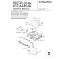
Screw driver (�)
Table 5-3-1.
Cover
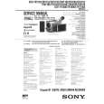
3-1-4. Connecting the Equipment Connect the measuring instruments as shown in Fig. 5-3-2 and perform the adjustments.
Connecting the TV Monitor and Regulated Power Supply
Battery terminal
Main Unit Regulated power supply 8.4 +0.1Vdc _ VIDEO
TV monitor
Connect when using the camera mode or playing back. VIDEO terminal