|
|
|
Who's Online
There currently are 6041 guests and
2 members online. |
|
Categories
|
|
Information
|
|
Featured Product
|
|
|
 |
|
|
There are currently no product reviews.
 ;
Very good service Within one day i received a pdf of the users manual and electric circuits so I was able to measure the different voltages in the printed circuit and find out the fault Payment was also reliable and easy.Without the manual i could not have repaired.So thanks to "Search for a manual"
 ;
you are doing great job guys.....my father ask me to find out the schematics of Sony KV25R1D to sort out the problem ..(he was electrical technician, and excperianced with TV and simillar stuff). finally he found the cause and change all necessary parts....now he has got working old dog..and is very happy!!... thank you all.. NB..he also saved the repair cost.
;
Perfect. Received my manual within 24 hours. Clear scan of the manual I needed. No problem.
;
Item as described, very well detailed manual with complete schematics. I've received the download information shortly after payment, very good support.
;
Really good and well scanned. File is complete the full service manual for 5$
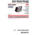
DV MECHANICAL ADJUSTMENT MANUAL VII
3-11.Band Adjuster, S Reel Table Assy and TG2 Arm Block Assy
1.
1) 2) 3) 4) 5)
Removal procedure
Remove the screw (special head screw M1.4 � 2.5) 1. Remove the band A of the TG2 arm block and remove the band adjuster 2. Remove the S reel table assy 3. Remove the tension spring (tension regulator spring) 4. Remove the TG2 arm block assy 5.
2.
1) 2)
Attachment procedure
Install the S reel table assy 3. Apply grease in the TG2 arm pivot shaft B. Amount of grease: a ball of 1.0 mm diameter of grease Re-application of grease to the point which is greased already before is not necessary. 3) Hold the TG2 arm block assy 5 with tweezers and insert it in the TG2 arm pivot shaft B. 4) Hook the tension spring (tension regulator spring) 4 on the TG2 arm block 5 with tweezers so that the hook faces downward. 5) Hook the tension spring (tension regulator spring) 4 on the LS chassis block assy (the second hook from the rear end). 6) Hook the A portion of the band on the claw of the band adjuster 2. 7) Hold the band adjuster with tweezers as shown in C. Insert the band into groove of the S reel table assy while rotating it, and insert the adjuster�s dowel into the dowel hole D of the LS chassis block assy. 8) Install the band adjuster 2 with the screw (special head screw M1.4 � 2.5) 1. Tightening torque: 0.059 ± 0.01N�m (0.6 ± 0.1kgf�cm) 9) Perform the TG2 FWD Position Adjustment referring to section 4-1. 10) Perform the FWD Back-tension Adjustment referring to section 4-4. 11) Perform the Reel Torque Check referring to section 4-2.
The spring hook faces downward. TG2 arm 5 block assy
3 S reel table assy
1 Screw (M1.4 � 2.5) 2 Band adjustor
4 Tension spring (Tension regulator)
A C
Dowel D Hole D Band
Shaft B
Key Points in Re-assembling
Second from the rear end The spring hook faces downward.
Apply Grease Points to be noted
During installation, apply grease in the TG2 arm pivot shaft hole. Amount of grease: a ball of grease of 1.0 mm diameter Re-application of grease to the point which is greased already before is not necessary. B
� 22 �
|
|
|
> |
|