|
|
|
Who's Online
There currently are 5795 guests online. |
|
Categories
|
|
Information
|
|
Featured Product
|
|
|
 |
|
|
There are currently no product reviews.
 ;
Very good service-manual with clear electrical diagrams. Thanks you.
 ;
the manual is in quite good quality and it's in pdf. manual was send in less then 6h.
;
Absolutely top, I've got now all Service-Manuals I'll need to repair my Mackie-Mixer!
;
The service manuel is very helpful, we where able to restore the device to its working operation again.
;
Great quality complete service manual!!! complete parts list and drawings
SERVICE NOTE
1. POWER SUPPLY DURING REPAIRS
In this unit, about 10 seconds after power is supplied to the battery terminal using the regulated power supply (4.2V), the power is shut off so that the unit cannot operate. This following two methods are available to prevent this. Take note of which to use during repairs. Method 1. Connect the servicing remote commander RM-95 (J-6082-053-B) to the LANC jack, and set the commander switch to the �ADJ� side. Method 2. Use the AC power adaptor (AC-VF10 or AC-VQ11) and connecting cord (DK-115).
B O
M A R R
2.
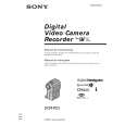
TO TAKE OUT A CASSETTE WHEN NOT EJECT (FORCE EJECT)
1 Refer to 2-2 to remove the accessory shoe and NS block assembly. 2 Refer to 2-2 to remove the jack ornamental plate. 3 Refer to 2-2 to remove the tripod screw. 4 Refer to 2-2 and 2-3 to remove the cabinet (R) block assembly. 5 Refer to 2-3 to remove the microphone unit. 6 Refer to 2-3 to remove the battery plate. 7 Refer to 2-3 to remove DD-125 board. 8 Refer to 2-3 and 2-4 to remove the cabinet (L) block assembly, lens block and EVF block. 9 Open MR-41 board. !º Disconnect CN2504 (4P, 0.8mm) of MR-41 board. !¡ Add +4.5V from the DC POWER SUPPLY and unload with a pressing the cassette compartment.
: Unloading : Loading
Disconnect from CN2504 of MR-41 board.
4D1
Loading motor
�6�
 $4.99 DCR-PC3 SONY
Owner's Manual Complete owner's manual in digital format. The manual will be available for download as PDF file aft…
|
|
|
> |
|