|
|
|
Who's Online
There currently are 5982 guests online. |
|
Categories
|
|
Information
|
|
Featured Product
|
|
|
 |
|
|
There are currently no product reviews.
 ;
Good quality, all schematics of few of models. There is also short form of user manual and regulation manual.
;
Perfect copy of the service manual. you can enlarge every page, and it comes up
with all details.
;
It´s very very nice manual with all, what i need. Original in good quality. Very fast business. Very much thanks...
;
Purchased the manual that I was looking for at a great price and could download it easily.. Great service experience and for future purchases I plan to use the site.
Thank you very much
;
Exactly what was needed to assess the product - excellent value and great service
DCR-IP210/IP210E/IP220/IP220E
3.
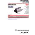
DISCHARGING OF THE FLASHLIGHT POWER SUPPLY CAPACITOR
The capacitor (ST-076 board C4208) of the flash unit is charged up to the maximum 300V potential. There is a danger of electric shock by this high voltage when the ST-076 board is handled by hand. The electric shock is caused by the charged voltage which is kept without discharging when the main power of the unit is simply turned off. Therefore, the remaining voltage must be discharged as described below. 3-1. PREPARING THE SHORT JIG To preparing the short jig. a small clip is attached to each end of a resistor of 1k� /1W (1-215-869-11). Wrap insulating tape fully around the reads of the resistor to prevent electric shock.
1 k �/1 W
Wrap insulating tape
3-2. DISCHARGING THE CAPACITOR 1 Remove the power supply (Battery or AC power adaptor). 2 Refer to 2-3. and 2-4. to remove the cabinet (F) assembly. 3 Short-circuit between TP4201 of the ST-076 board and the LND421 (GND) with the short jig about 10 seconds.
Short jig 1k�/1W resister
TR4201
C4208
LND421
ST-076 board
4.
HOW TO OPEN THE FLASH WHEN THE FLASH DOESN�T OPEN
1 Remove the power supply (Battery or AC power adaptor). 2 Refer to 2-2. to remove the front cap assembly. 3 Press the Stopper in the direction of the arrow using a rod.
Stopper
5.
COAXIAL CONNECTOR OF THE BLUETOOTH HARNESS (DCR-IP220/IP220E model)
When the coaxial connector of the Bluetooth harness isn�t pulled out vertically toward the board, the connector may be damaged. So, when disconnecting the connector, be sure to take the connector of the Bluetooth harness, and pull iPress the Stopper in the direction of the arrow using a rod/t out vertically toward the board.
Connector of the Bluetooth harness Bluetooth harness
1-2
|
|
|
> |
|