The service manual was very usable and clear enough to see the individual values of all of the components (unlike some of the service manuals I have gotten in the past from web sites similar to this one). The price was right and the information was greatly appreciated. It helped me with an otherwise very difficult repair. It was much needed and appreciated. A faster turn around on my order would be nice, but I understand the constraints on your staff's time. Thank you for your service.
I liked the price plus it had everything i needed to service the tv.
thankyou Tim Hertz
Text excerpt from page 343 (click to view)
DV MECHANICAL ADJUSTMENT MANUAL VII
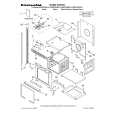
3-11.Band Adjuster, S Reel Table Assy and TG2 Arm Block Assy
1.
1) 2) 3) 4) 5)
Removal procedure
Remove the screw (special head screw M1.4 � 2.5) 1. Remove the band A of the TG2 arm block and remove the band adjuster 2. Remove the S reel table assy 3. Remove the tension spring (tension regulator spring) 4. Remove the TG2 arm block assy 5.
2.
1) 2)
Attachment procedure
Install the S reel table assy 3. Apply grease in the TG2 arm pivot shaft B. Amount of grease: a ball of 1.0 mm diameter of grease Re-application of grease to the point which is greased already before is not necessary. 3) Hold the TG2 arm block assy 5 with tweezers and insert it in the TG2 arm pivot shaft B. 4) Hook the tension spring (tension regulator spring) 4 on the TG2 arm block 5 with tweezers so that the hook faces downward. 5) Hook the tension spring (tension regulator spring) 4 on the LS chassis block assy (the second hook from the rear end). 6) Hook the A portion of the band on the claw of the band adjuster 2. 7) Hold the band adjuster with tweezers as shown in C. Insert the band into groove of the S reel table assy while rotating it, and insert the adjuster�s dowel into the dowel hole D of the LS chassis block assy. 8) Install the band adjuster 2 with the screw (special head screw M1.4 � 2.5) 1. Tightening torque: 0.059 ± 0.01N�m (0.6 ± 0.1kgf�cm) 9) Perform the TG2 FWD Position Adjustment referring to section 4-1. 10) Perform the FWD Back-tension Adjustment referring to section 4-4. 11) Perform the Reel Torque Check referring to section 4-2.
The spring hook faces downward. TG2 arm 5 block assy
3 S reel table assy
1 Screw (M1.4 � 2.5) 2 Band adjustor
4 Tension spring (Tension regulator)
A C
Dowel D Hole D Band
Shaft B
Key Points in Re-assembling
Second from the rear end The spring hook faces downward.
Apply Grease Points to be noted
During installation, apply grease in the TG2 arm pivot shaft hole. Amount of grease: a ball of grease of 1.0 mm diameter Re-application of grease to the point which is greased already before is not necessary. B