|
|
|
Who's Online
There currently are 6042 guests online. |
|
Categories
|
|
Information
|
|
Featured Product
|
|
|
 |
|
|
There are currently no product reviews.
 ;
The manual was very accurate for the part that I was changing, I was able to order the correct part and had no issues with the replacement procedure. However, I was expecting to have more detailed repairs for the lower drive unit.
 ;
I needed the manual immediately and I got it immediately. I couldn't find this manual anywhere else on the net. The site was easy to traverse, and the price was very reasonable. I'll definitely be back for any future needs.
;
I received a good service manual, with good resolution. Improve the instructions for the purchase because they are not well understood.
For the rest, so good.
Thanks Angel.
;
Very good documentation for the Grundig 2077 model (as well as similar 800/900/1000 series radios). The first two pages are a summary of reception specifications and output capability. The third page is the tuner dial indicator and dial cord routing diagram. the final ~5 pages are the schematics for the various models (including 2077). The scan quality of the schematics are good, adn can be easily read if zoomed in. The documents are in German, not English as stated. It would have been nice to have the tuning sequence and settings, and some trouble shooting materials... or component and wiring map.
;
Perfect like it was descriped, Perfect like it was descriped
CX-JN44 SECTION 5 ELECTRICAL CHECK
Note: 1. CD Block is basically constructed to operate without adjustment. 2. Use YEDS-18 disc (3-702-101-01) unless otherwise indicated. 3. Use an oscilloscope with more than 10 M� impedance. 4. Clean the object lens by an applicator with neutral detergent when the signal level is low than specified value with the following checks. 5. Check the focus bias check when optical block is replaced. FOCUS BIAS CHECK
oscilloscope (DC range) BD board TP012 (RFACO) TP013 (VC)
+ �
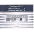
Procedure : 1. Connect the oscilloscope to TP012 (RFACO) and TP013 (VC) on the BD board. 2. Insert the disc (YEDS-18). (Part No. : 3-702-101-01) 3. Press the H button. 4. Confirm that the oscilloscope waveform is as shown in the figure below. (eye pattern) A good eye pattern means that the diamond shape (�) in the center of the waveform can be clearly distinguished. � RF signal reference waveform (eye pattern)
VOLT/DIV: 0.2 V (with the 10: 1 probe in use.) TIME/DIV: 500 ns
1.1
0.2 Vp-p
When observing the eye pattern, set the oscilloscope for AC range and raise vertical sensitivity.
Checking Location: � BD BOARD (Conductor Side) �
TP012 (RFACO)
TP013 (VC)
21
21
|
|
|
> |
|