|
|
|
Who's Online
There currently are 5973 guests online. |
|
Categories
|
|
Information
|
|
Featured Product
|
|
|
 |
|
|
There are currently no product reviews.
 ;
This is a high quality manual with clear schematic and components layout diagrams ; with service procedure included.
 ;
This service manual for the Kenwood KT-990D was reproduced really well ,is very legible and manual is complete.Combined with the low price paid,in the future,I will be checking Owner-Manuals.com any time I need a manual.
;
When I purchased this manual I had my doubts regarding the quality as the price was so reasonable as compared to other outlets.
The manual itself is of high standard the print is very clear as are the diagrams. Obviously with the diagrams one has to zoom in otherwise it is to small to be able to read.
Overall I am very pleased with the company who delivered as they said and with the manual they supplied.
I occasionally require a manual and now having registered with this company I shall order from them in the future.
;
I was at first dubious about payiong for downloaded manuals but having done so, I was extremely impressed with quality of the two manual I ordered, well worth the small price I paid.
I would highly recommend these to my friends.
;
reasonable price for the schematic - the service is perfect, all as expected and pointed by instructions - good scan of the original plans - thank you!
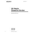
TUNER SECTION
0 dB = 1 µV
FM FREQUENCY COVERAGE Frequency Display Adjustment Part ADJUSTMENT 87.5 MHz 1.6 ± 0.4 V <confirmation> 108 MHz 4.0 ± 0.1V L2
� FM Section Setting: RADIO (BAND) button: FM
FM RF signal generator TP (FM ANT) 0.01 µF
set
75 kHz frequency deviation by 1 kHz signal output level : as low as possible
Reading on Digital voltmeter
FM TRACKING ADJUSTMENT Adjust for a maximum reading on level meter. L1 87.5 MHz CT1 108 MHz
AM FREQUENCY COVERAGE CHECK � AM Section Setting: RADIO (BAND) button: AM
AM RF signal generator Put the lead-wire antenna close to the set.
Frequency Display Reading on Digital voltmeter Adjustment Part
530 kHz 1.0 + 0.7 V � 0.5 V
1,710 kHz 4.8 + 1.2V � 0.6 V
<confirmation> <confirmation>
AM TRACKING ADJUSTMENT Adjust for a maximum reading on level meter. L4 620 kHz CT3 1,400 kHz
30% amplitude modulation by 400 Hz signal
� For AM adjustment, fix the ferrite-rod antenna (L3) as shown below and then perform tracking adjustment at L4 and CT3. Lastly check the voltage.
3.0 ± 1.0 mm
level meter (range: 0.5�5 V ac) 32 �
� Connecting Level Meter (FM and AM)
set
2 jack (J301)
L3 AM FERRITE-ROD ANTENNA
Adjustment Location: See page 14. � Connecting Digital Voltmeter (FM and AM)
digital voltmeter 100 k� TP (VT) (JW17)
� Repeat the procedures in each adjustment several times, and the frequency coverage and tracking adjustments should be finally done by the trimmer capacitors.
� 13 �
 $4.99 CFD-S38 SONY
Owner's Manual Complete owner's manual in digital format. The manual will be available for download as PDF file aft…
|
|
|
> |
|