|
|
|
Who's Online
There currently are 5805 guests online. |
|
Categories
|
|
Information
|
|
Featured Product
|
|
|
 |
|
|
There are currently no product reviews.
 ;
Super nice! Good to have a manual in digital format.
;
Great job supplying the manual.
Many of these products weerepretty obscure, so it was great that you had
the manual for it!
;
Great manual, would not have been able to operate my machine without it!!
James Dawson August 18, 2012
;
excellent value & price! Includes everything you need to know about the NN-C777! I would buy this again.
;
Very satisfied! I was searching for several days, but nope; till I discovered your webside and there it was at a very reasonable price. Keep up the good work!
Paul
Flanders
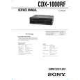
Connections
Caution
�This unit is designed for negative ground 12 V DC operation only. �Before making connections, disconnect the ground terminal of the car battery to avoid short circuits. �Connect the yellow and red power input leads only after all other leads have been connected. �Be sure to connect the red power input lead to the positive 12 V power terminal which is energized when the ignition key is in the accessory position. �Run all ground wires to a common ground point. �Connect the yellow cord to a free car circuit rated higher than the unit�s fuse rating. If you connect this unit in series with other stereo components, the car circuit they are connected to must be rated higher than the sum of the individual component�s fuse rating. If there are no car circuits rated as high as the unit�s fuse rating, connect the unit directly to the battery. If no car circuits are available for connecting this unit, connect the unit to a car circuit rated higher than the unit�s fuse rating in such a way that if the unit blows its fuse, no other circuits will be cut off. �The use of optical instruments with this product will increase eye hazard.
Installation
Parts for Installation and Connections 1
TOP
The numbers in the list are keyed to those in the instructions.
Precautions
3
�Do not tamper with the four holes on the upper surface of the unit. They are for tuner adjustments to be done only by service technicians. �Choose the installation location carefully so that the unit will not hamper the driver during driving. �Avoid installing the unit where it would be subject to high temperatures, such as from direct sunlight or hot air from the heater, or where it would be subject to dust, dirt, or excessive vibration. �Use only the supplied mounting hardware for a safe and secure installation.
2
Mounting angle adjustment
Adjust the mounting angle to less than 60°.
4
5
6
Mounting example
Installation in the dashboard
182
1
�2
m
m(
7/
1
4
in
.)
2
53 mm (2 1/8 in .)
3
5� 7 max.�size in.) 6 mm (7/32 1/4
Reset button
When the installation and connections are complete, be sure to press the reset button with a ball-point pen, etc.
7
8
9
TO P
6 6 1
Bend these claws, if necessary. Note To prevent malfunction, install only with the supplied screws 7.
7
6
7 max. size 5 � 6 mm
(7/32 � 1/4 in.)
AMS SHUF
REPEAT
�4
DSPL OFF
With the TOP marking up
Reset button
Caution
Cautionary notice for handling the bracket 1. Handle the bracket carefully to avoid injuring your fingers.
TOP
4
1 2
To support the unit
Dashboard
Fire wall
2 3 max. size M4 � 6 mm
(3/16 � 1/4 in.)
TO P
4 Connection example 5
With the TOP marking up
1
To a metal point of the car
First connect the black ground lead, then connect the yellow and red power input leads.
Black 0.5 m (1 ft. 8 in.)
Blue/White 0.5 m (1 ft. 8 in.) AMP REMOTE OUT Max. supply current 0.3 A
To AMP REMOTE IN of the car audio*1
Mounting the unit in a Japanese car
You may not be able to install this unit in some makes of Japanese cars. In such a case, consult your Sony dealer.
To the +12 V power terminal which is energized in the accessory position of the ignition key
Be sure to connect the black ground lead first.
Fuse
Red 0.5 m (1 ft. 8 in.) *1 You can only connect a car audio which has both a remote amplifier input (AMP REMOTE IN) and an audio input (AUDIO IN).
TOYOTA 7 max. size 5 � 6 mm
(7/32 � 1/4 in.) Car audio with FM tuner to dashboard/center console
NISSAN 7 max. size 5 � 6 mm
(7/32 � 1/4 in.) Car audio with FM tuner to dashboard/center console
To the +12 V power terminal which is energized at all times
Be sure to connect the black ground lead first.
Fuse
Yellow 0.5 m (1 ft. 8 in.)
Note Do not connect an external amplifier to the audio output (AUDIO OUT) of this unit. Otherwise, the volume of the connected speakers cannot be adjusted.
8
AUDIO OUT
Bracket
L R
AUDIO OUT
7 max. size 5 � 6 mm
(7/32 � 1/4 in.) Bracket CDX-1000RF
7 max. size 5 � 6 mm
(7/32 � 1/4 in.)
To AUDIO IN of the car audio*1
CDX-1000RF
RCA pin cord
Bracket
Bracket
REMOTE IN
(not supplied) Existing parts supplied with your car Existing parts supplied with your car
From car antenna 1.9 m (6 ft. 3 in.) Rotary commander RM-X4S*2 (not supplied) 0.5 m (1 ft. 8 in.) Antenna connector*3
Note To prevent malfunction, install only with the supplied screws 7.
Removing the unit
Car audio Speaker system
If you have a Sony car audio with the Sony BUS terminal, the optional source selector XA-107 can be used in your system.
1
Sony car audio *2 You can also control the following functions with the rotary cammander RM-X4S: Power on � Press SOURCE. Power off � Press OFF. Locate a specific track � Rotate the SEEK/AMS control momentarily and release. Locate a specific point within a track � Rotate the SEEK/AMS control and release when the desired point is found. Adjust the volume � Rotate the volume control. *3 An adaptor (optional) may be necessary for your car and car audio system. In such a case, consult your dealer.
Insert the supplied tool 9 between the unit and the frame, and rotate 90° to release the hidden mounting spring. Repeat on the opposite side and remove the frame.
2
Insert a flathead screwdriver between the bracket and mounting spring. Gently pry the spring toward the unit while pulling the unit out a little. Repeat on the opposite side and remove the unit.
AUDIO IN
BUS CONTROL IN
AUDIO OUT
MASTER
Source selector XA-107
4 mm (3/16 in.)
9 AUDIO IN AUDIO OUT
90º CDX-1000RF 10 mm (13/32 in.)
|
|
|
> |
|