|
|
|
Who's Online
There currently are 5976 guests online. |
|
Categories
|
|
Information
|
|
Featured Product
|
|
|
 |
|
|
There are currently no product reviews.
 ;
Great service manua!
Always great value and fast service A++++++++++++++++++
;
Excellent Service manual, good quality scans, quick service and very good value. Well reccomended ! All good.
;
Great value service manual!
Good-quality scans. Detailed and valuable informations.
A+++++++++++++++
;
Great value service manual!
Good-quality scans. Detailed and valuable informations.
A+++++++++++++++
;
Excellent scan quality. A complete and very useful manual with all details.
Great service at low price A+++++++++++++++++
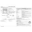
DISC IN DETECT SENSOR ADJUSTMENT Be sure to perform this adjustment after sensor adjustment in MECHANICAL ADJUSTMENT. Connection:
MAIN board TP1 T.P GND D.S T.P: Pin 1 D.S: Pin 3 GND: Pin 2 oscilloscope (DC range)
D.S
T.P
Waveform:
Should be at the center
D.S
T.P
5. Rotate the [DISC/CHARACTER] knob in the counterclockwise direction and the disc table starts to rotate in the same direction. Check that the waveform at this time is the same as that in step 4. If larger by a considerable extent, rotate the [DISC/CHARACTER] knob in the clockwise direction and the disc table starts to rotate in the same direction. Repeat from step 4. 6. Rotate RV501 of the MAIN board and adjust so that the H and L portions of the D.S waveform become the same.
1. Connect the oscilloscope to Pins 1, 2, and 3 of TP1 of the MAIN board. 2. Check that no discs are loaded in the unit. 3. With the power ON, while pressing the [GROUP FILE] and [MEGA CTRL] buttons, press the I/1 button. Rotate the [DISC/ CHARCTER] knob, select �Table Rotation� and press the knob. The disc table starts to rotate in the clockwise direction. 4. Loosen the fixing screw, move the mounting board (SENSOR), and secure the mounting board (SENSOR) at the point the H portion of the P.T waveform comes the center of the H portion of the D.S waveform.
D. SENS (OUT) board
D.S Adjust so that these widths become the same.
Adjustment Location: MAIN board
S tight, screw (PTTWH 3 � 6)
20
|
|
|
> |
|