|
|
|
Who's Online
There currently are 5974 guests online. |
|
Categories
|
|
Information
|
|
Featured Product
|
|
|
 |
|
|
There are currently no product reviews.
 ;
The Manual was perfect.
The deliverie was perfect.
Thanks
;
Found website easy to use and manual very clear. First class service
 ;
The quality is quite good and clear. Nothing of the informations inside is lost during the digitalizing process
;
Very good service, fast downloads and good manuals.
;
Good qulity. Even as it is an old manual (from 1991-1992) it has a good scanned quality and is complete, including user's manual, disassembly intructions, diagrams and schematics, ajustments, troubleshooting and parts list, as usual with SONY manuals and Owner-manuals service.
CDP-CE275/CE375
Ver 1.1 2001.07
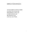
E-F Balance Check Connection:
oscilloscope BD board TP (TE1) TP (VC)
+ �
Checking Location: � BD BOARD (Conductor Side) �
Procedure: 1. Set the test disc (PATD-012). Disc chucking operation is complete, then press the [POWER] button to turn the power off. 2. Connect an oscilloscpe to test point TP (TE1) and TP (VC) on the BD board. 3. Connect between test point TP (ADJ) on the MAIN board and GND by lead wire. 4. Press the [POWER] button to turn the power on and enter the ADJ mode, then playback the number two track automatically. 5. Press the [TIME] button. (The tracking servo and the sledding 6. servo are turned OFF) Check the level B of the oscilliscope waveform and the A (DC voltage) of the center of the Traverse waveform. Confirm the following : A/B x 100 = less than ± 22%
Traverse Waveform
Center of the waveform B 0V A (DC voltage) level: 1.15 ± 0.5 Vp-p
IC150 TP (VC)
IC131 TP (TE1)
TP (FE1) IC101
TP (RFDC)
TP (RFAC)
7.
Press the [TIME] button. (The tracking servo and sledding servo are turned ON) Confirm the C (DC voltage) is almost equal to the A (DC voltage) is step 6.
Traverse Waveform
0V
C (DC voltage) Tracking servo Sled servo OFF Tracking servo Sled servo ON
Checking Location: BD board
14
|
|
|
> |
|