|
|
|
Who's Online
There currently are 6043 guests online. |
|
Categories
|
|
Information
|
|
Featured Product
|
|
|
 |
|
|
There are currently no product reviews.
 ;
A very well written and easy to understand manual.
;
There was no problem at all.After paying i had to wait only a few hours,than i could
download the manual in best pdf-quality.
Thank You !
 ;
I found this service manual to be complete in every detail except for troubleshooting charts. It would be helpful if it had a set of troubleshooting charts; however it is a very good manual otherwise and for the price it is very well worth it.
;
Complete manual included schematics layouts and alignment procedure, clear to read and magnify, extremely pleased with manual and owner manual . com's service
;
perfect, i am very satisfait for the réception of the sansui r-5l service manual, thank you very much
1-1-3.Precaution 1. Setting the Switch Unless otherwise specified, set the switches as follows and perform adjustments without loading cassette. 1. POWER switch (MA-311 board) .......................... CAMERA 2. NIGHT SHOT switch (Lens block) ................................ OFF (Night shot model) 3. VIDEO LIGHT switch (MA-311 board) ........................ OFF (Video light model) 4. DEMO MODE (Menu display) ....................................... OFF 5. DIGITAL ZOOM (Menu display) ................................... OFF 2. Adjusting Procedure Adjust in the given order.
Yellow
6. STEADY SHOT (Menu display) .................................... OFF 7. FOCUS switch (MF-8500) .................................... MANUAL (Manual focus model) 8. PROGRAM AE (CF-49 board) ....................................... Auto 9. BACK LIGHT (CF-49 board) ......................................... OFF 10. PICTURE EFECT (CF-49 board) ................................... OFF 11. 16 : 9 WIDE (MENU display) ........................................ OFF
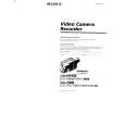
Color bar chart standard picture trame H Green White Magenta Cyan 0 ± 0.1 msec Magenta Yellow Green White Cyan Blue Red
Blue
Electronic beam scanning frame
Red
CRT picture frame
V AB A=B BA Fig. b. (TV monitor picture) Enlargement Fig. a. (Video output terminal output wavefom) Difference in level
A
B
Adjust the camera zoom and direction to obtain the output wavefom shown in Fig. a and the TV monitor display shown in Fig. b.
Fig. 5-1-4.
3. Subject 1) Color bar chart (Standard picture frame) Adjust the picture frame as shown in Fig. 5-1-4. if adjustments are performed using the color bar chart. (Standard picture frame) 2) White pattern (Standard picture frame) Remove the color bar chart from the pattern box, and insert a clear chart in its place. (Do not perform zoom operations during this time.) 3) Chart for flange back adjustment Combine a white A0 size (1189 mm x 841 mm) paper to a black one, and make the chart shown in Fig. 5-1-5.
Black
White 841 mm
1189 mm
Fig. 5-1-5.
Note : Use the non-reflecting and non-glazing vellum paper whose size is more than A0, and make the boundary between white and black to be smoothly flat.
5-5
|
|
|
> |
|