|
|
|
Who's Online
There currently are 6041 guests and
2 members online. |
|
Categories
|
|
Information
|
|
Featured Product
|
|
|
 |
|
|
There are currently no product reviews.
 ;
Excellent quality. Easy process to download. No issues or problems at all - was exactly what I was looking for and needed. Great service.
;
I was having a hard time finding the problem with this Mackie 1604 unit. I didn't have a schematic. Went looking on the web and found your site and the price was more then reasonable. Ordered it and within the hour had the manual and within 15 minutes had the unit fixed. Best $4.99 I ever spent. Thank you.
Doug
;
This is a service manual in every sense of the word ( French and German versions of the text are included, as well as English..)
There are explanations of the mechanical and electrical functions, plenty of mechanical drawings, and the needed schematics. The quality of the scanning is excellent - all the component values are clearly legible - and very usefully there are pcb component layouts, so you can find a component on the schematic, and then very quicky pinpoint its physical location on the relevant pcb.
I cannot see how I can give this manual any less than the maximum 5 stars! Great value for money, which will pay for itself immediately. Excellent all round!
;
the manual is great and especially hard to find... thanks for the great service and having a hard to find manuel_
;
Please tell us what you think and share your opinions with others. Be sure to focus your comments on the product. You will receive $2.50 of store credit for Your review.
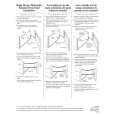
SERVICE NOTE
1. POWER SUPPLY DURING REPAIRS
In this unit, about 10 seconds after power is supplied (8.4V) to the battery terminal using the service power cord (J-6082-223-A), the power is shut off so that the unit cannot operate. This following three methods are available to prevent this. Take note of which to use during repairs. Method 1. Connect the servicing remote commander RM-95 (J-6082-053-B) to the LANC jack, and set the remote commander switch to the �ADJ� side. Method 2. Press the battery switch of the battery terminal using adhesive tape, etc. Method 3. Use the DC IN terminal. (Use the AC power adaptor.)
DC IN terminal Battery SIG terminal Battery terminal �
Battery switch
Battery terminal �
2. TO TAKE OUT A CASSETTE WHEN NOT EJECT (FORCE EJECT)
1 Refer to 2-1. to remove the front panel block. 2 Refer to 2-4. to remove the cabinet (R) assembly. 3 Refer to 2-6. to remove the battery panel block. 4 Refer to 2-7. to remove the cabinet (L) block. 5 Add +5V from the DC POWER SUPPLY and unload with a pressing the cassette lid.
6
Pull the timing belt in the direction of arrow A with a pinsette while pressing the cassette lid (take care not to damage) to adjust the bending of a tape.
A
Pinsette
Press the cassette lid not to rise the cassette compartment [DC power supply] (+5V)
Timing belt
7
Let go your hold the cassette lid and rise the cassette compartment to take out a cassette.
+
�
Loading motor Adjust the bending of a tape
Timing belt
�5�
|
|
|
> |
|