|
|
|
Who's Online
There currently are 5792 guests online. |
|
Categories
|
|
Information
|
|
Featured Product
|
|
|
 |
|
|
There are currently no product reviews.
 ;
It was magic after so many years to still be able to source this info. It was equally amazing to return my Pioneer receiver to it near new sound quality AFTER NEARLY 30 YEARS! Thank you for this ability!
;
Very quick and easy website to use and fast download of manual, quality of manual is excellent and will be pleased to use this service again in the future, thanks so much!
 ;
Easy and secure way to get a complete service manual of a vintage hifi component. Only some parts of the print copy are dificult to read. Nice price!
;
The manual is an excellent reproduction with complete schematics, made troubleshooting and repair a simple process.
;
Up to now you are the BEST! Prompt-efficient and so reasonable ! I have been after SONY service manual for quite some time !Thank you very much ! I can recomend your service to
all my collegagues ! V.Bergfield .
2-4. Software Update 2-5. Notes on Repair Parts
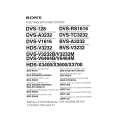
2-4-3. Flash Memory Replacement
1. Remove the top plate. (Refer to �2-1. Cabinet Removal/Installation�.) 2. Remove and replace the flash memory on the CPU244 board (IC7) using an IC extraction tool. Sony part number of IC extraction tool: J-6035-070-A n If the flash memory is difficult to be removed by the IC extractor, use the tweezers or equivalent.
2-5. Notes on Repair Parts
w Use the specified parts only Components marked ! are critical to safe operation. Therefore, specified parts in the section of Spare Parts should be used in the case of replacement. 1. Safety Related Components Warning Components marked ! are critical to safe operation. Therefore, specified parts should be used in the case of replacement. 2. Standardization of Parts Some repair parts supplied by Sony differ from those used for the unit. These are because of parts commonality and improvement. Parts list has the present standardized repair parts. 3. Stock of Parts Parts marked with �o� at SP (Supply Code) column of the spare parts list may be not stocked. Therefore, it may take a long time to deliver. 4. Units Representation The following represented units are changed or omitted in writing.
Units Capacitance Inductance Resistance Temperature uF uH Z dC Representation uF uH Abbreviation XXX-DEG-C
Flash Memory (IC7)
CPU-244 board
3.
While pressing the button 1 and 2 of the front panel at the same time, turn the power switch ON to initialize the unit. c If the unit is initialized, all setting data is back to default setting. Reset the setting or copy the data from another control unit. (For the details of setting, refer to the operation manual supplied with the unit.)
BKS-R1607/R1608 BKS-R3209/R3210
2-7(E)
|
|
|
> |
|