|
|
|
Who's Online
There currently are 5981 guests online. |
|
Categories
|
|
Information
|
|
Featured Product
|
|
|
 |
|
|
There are currently no product reviews.
 ;
Impressively thorough. Even the simple operators manual helped me "fix" one of the 2 CD players in the unit. This unit reads CD's from the top so they should be installed in the magazines "upside down" from typical CD players. The CD player service manual helped me unjam a stuck carriage because somebody transported the box laying down loaded with CD's. A little lens cleaning & the player now works well! Thanks for you help at a great price! Joe
;
I was skeptical at first but later found the manual to be good quality for the price. It took a couple hours to receive the email with the download link, well worth the wait. Thanks.
;
very helpful, I could not have cleaned motherboard and replaced the main fan without it
 ;
Good manual, schematics nice and clear with good quality scanning. Woul dhave been nice to have immediate access after purchasing though.
;
I was very glad recieving the service manal from You. Manuals were delivered promptly and were correct as advertised. A complete and very usefull service manual with all details. Thank you!
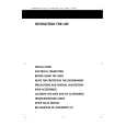
1-4. Location and Function of Switches/LEDs
6 D3: SYNCHRO (synchronization) indicator Lights green : When the video signal input to the SDI IN connector is within the range set using the SYNCHRO MODE (S11), and a reference signal is input to the REF IN connector with the LOCK MODE switch (S6) is sellected to the �REF�. Lights red : When the video signal input to the SDI IN connector is out of the range set using the SYNCHRO MODE switch (S11). Lights off : When the LOCK MODE switch (S6) is selected to the �INPUT�. 7 D6:OVER FLOW indicator Lights red : If the arithmetic operation result overflows when a 4:2:2 component serial digital video signal is converted into a composite signal. Usually, this lamp lights off. 8 S4 and S5: V BLK SELECT switches Turned on and off the blanking for each line during the vertical blanking period of an analog signal output from the ANALOG OUT connector. The lines in the first and second fields corresponding to the switches are blanked when these switches are set to ON. S4 S4-1 : 22 and 335 S4-2 : 21 and 334 S4-3 : 20 and 333 S4-4 : 19 and 332 S4-5 : 18 and 331 S4-6 : 17 and 330 S4-7 : 16 and 329 Factory setting: all OFF S5 S5-1 : 15 and 328 S5-2 : 14 and 327 S5-3 : 13 and 326 S5-4 : 12 and 325 S5-5 : 11 and 324 S5-6 : 10 and 323
9 S2:TEST SG(test signal) switches Outputs a test signal. S2-1: ON : Outputs a test signal (color-bar signal) from the ANALOG OUT connector. OFF : Normal operation Factory setting: OFF S2-2: (Not used.) Factory setting: OFF 0 S8:SYSTEM RESET switch Press to reset the CPU. n At the instant of pushing this switch cause jitter of the image. !- S12 : SCH adjust switches Used to adjust the SCH phase. When you set a switch to ON, the phase will shift by the amount corresponding to the switch shown in the following table. If you set two or more switches to ON, the phase will shift by the total amount of the corresponding switches.
Switch No. S12-1 S12-2 S12-3 S12-4 S12-5 S12-6 S12-7 S12-8 S12-9 S12-10 Amount of the adjustment (�) 0.35 0.70 1.41 2.81 5.63 11.3 22.5 45.0 90.0 180.0
Factory setting: S12-4, -5, -6, -7, -8, -9 ; ON S12-1, -2, -3, -10 ; OFF != S1: Free-running adj. switch Factory setting: OFF
BKPF-132BP
1-5
|
|
|
> |
|